


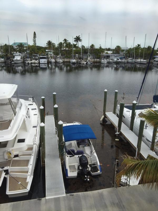
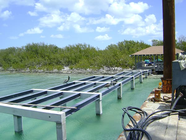
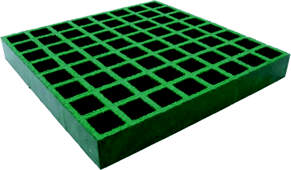
Docks & Piers in severe weather prone areas tend to suffer substantial damage after a storm. Wood planks become loose and break off or are lifted up from the storm surge and wash away.
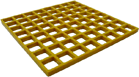
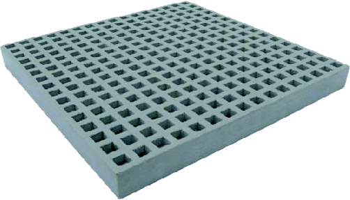
Environmental Composites offers high flow-thru fiberglass grating that allows the water from a storm surge to flow through the grate openings so the grating stays in place and does not wash away.
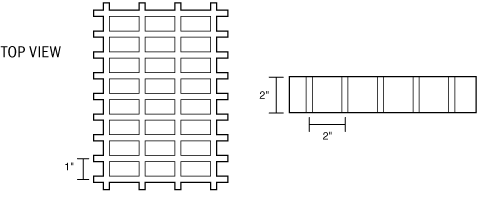
We recommend a ¾” square grid, 1” or 1-1/2” thick that is durable, attractive and very easy on bare feet.
Environmental Composites also offers fiberglass structural materials including square tube, channel, I Beam & Angle that make excellent materials for designing and building your dock or pier structure.
Our fiberglass is UV and corrosion resistant which makes it the optimal choice for building materials in dock applications.
Please contact us today at (352) 343-3449 or reach out to us on our online contact form for more information about our hurricane solutions.
Available Resin Systems
Molded grating is available in three resin systems, each providing different levels of corrosion protection. All three resin systems meet Class 1 Flame Spread Rating per ASTM E-84 test standards.
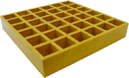
GP: A general-purpose orthophthalic polyester resin system that offers good corrosion resistance at an economical price. Standard colors: Yellow and Light Gray.
IFR: A premium-grade isophthalic polyester resin system that provides excellent corrosion protection. Standard colors: Green, Yellow, Dark Gray and Light Gray.
VFR: A vinylester resin system that provides the highest level of corrosion protection. Standard colors: Orange and Dark Gray.
Available Top Surfaces
Molded grating is available in square or rectangular mesh patterns with either Meniscus or Grit-Top slip-resistant top surfaces.
Grit-Top: Quartz grit anti-slip surface.
Meniscus: Concave, half-moon cross section with no grit.
Mini-Mesh: The best solution for docks and piers.
Available Grid Dimensions
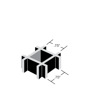 1" or 1½" thick | 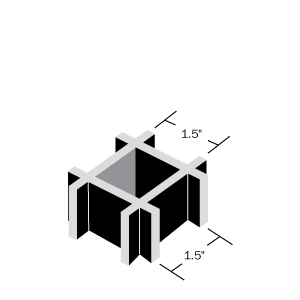 1" or 1½" thick | 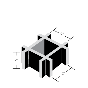 2" thick | 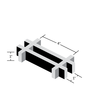 1" thick | 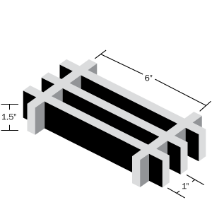 1½" thick |
Available Panel Sizes
| Grid Dimension | Available Panel Sizes |
|---|---|
| 1" x ¾" x ¾" (Square) | 4' wide x 12' long |
| 1½" x ¾" x ¾" (Square) | 4' wide x 12' long |
| 1" x 1½" x 1½" (Square) | 3' wide x 10' long, 4' wide x 8' long, 4' wide x 12' long |
| 1½" x 1½" x 1½" (Square) | 3' wide x 10' long, 3' wide x 12' long, 4' wide x 12' long |
| 2" x 2" x 2" (Square) | 4' wide x 12' long, 5' wide x 12' long |
| 1" x 1" x 4" (Rectangular) | 4' long x 12' wide, 3' long x 10' wide |
| 1½" x 1" x 6" (Rectangular) | 4' wide x 12' long |
To view load data for our molded grating, click on a size below.
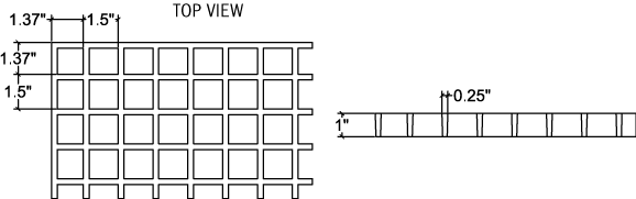
1" Thick 69% Open
| Span (inches) | CONCENTRATED LOAD in lb/ft of width | Max Load (lb/ft) | Apparent EI x 106 (lb-in2) | |||||||
|---|---|---|---|---|---|---|---|---|---|---|
| 50 | 100 | 150 | 200 | 250 | 500 | 1000 | 2000 | |||
| 12 | 0.006 | 0.011 | 0.017 | 0.023 | 0.029 | 0.057 | 0.114 | 1189 | 0.31 | |
| 18 | 0.018 | 0.035 | 0.053 | 0.071 | 0.089 | 0.177 | 934 | 0.34 | ||
| 24 | 0.040 | 0.080 | 0.120 | 0.160 | 0.199 | 0.399 | 668 | 0.36 | ||
| 30 | 0.076 | 0.152 | 0.228 | 0.304 | 0.380 | 534 | 0.37 | |||
| 36 | 0.128 | 0.256 | 0.384 | 0.512 | 0.640 | 360 | 0.38 | |||
| Span (inches) | UNIFORM LOAD in lb/ft of width | Max Load (lb/ft) | Apparent EI x 106 (lb-in2) | |||||||
|---|---|---|---|---|---|---|---|---|---|---|
| 50 | 100 | 150 | 200 | 250 | 500 | 1000 | 2000 | |||
| 12 | 0.004 | 0.007 | 0.011 | 0.014 | 0.018 | 0.036 | 0.071 | 0.143 | 2378 | 0.31 |
| 18 | 0.017 | 0.033 | 0.050 | 0.066 | 0.083 | 0.166 | 0.332 | 1245 | 0.34 | |
| 24 | 0.050 | 0.100 | 0.150 | 0.199 | 0.249 | 0.498 | 668 | 0.36 | ||
| 30 | 0.119 | 0.237 | 0.356 | 0.475 | 0.593 | 427 | 0.37 | |||
| 36 | 0.240 | 0.480 | 240 | 0.38 | ||||||
| 42 | 0.431 | 205 | 0.39 | |||||||
| Properties Per Foot of Width | # of Bars | Load Bar Width | Bar Centers | Weight/sq ft |
|---|---|---|---|---|
| A = 1.79 in2 I = 0.15 in4 S = 0.30 in3 | 8 | 0.25" | 1.5" | 2.5 |
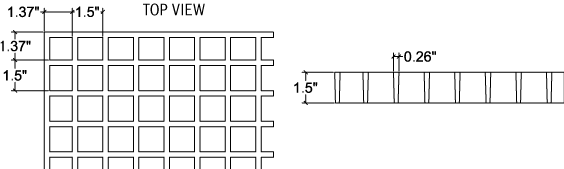
1½" Thick 68% Open
| Span (inches) | CONCENTRATED LOAD in lb/ft of width | Max Load (lb/ft) | Apparent EI x 106 (lb-in2) | |||||||
|---|---|---|---|---|---|---|---|---|---|---|
| 50 | 100 | 150 | 200 | 250 | 500 | 1000 | 2000 | |||
| 12 | 0.002 | 0.005 | 0.007 | 0.009 | 0.011 | 0.023 | 0.045 | 0.090 | 2041 | 0.80 |
| 18 | 0.005 | 0.011 | 0.016 | 0.022 | 0.027 | 0.055 | 0.109 | 1360 | 1.11 | |
| 24 | 0.012 | 0.023 | 0.035 | 0.046 | 0.058 | 0.115 | 0.230 | 1021 | 1.25 | |
| 30 | 0.021 | 0.043 | 0.064 | 0.086 | 0.107 | 0.214 | 816 | 1.31 | ||
| 36 | 0.036 | 0.072 | 0.108 | 0.144 | 0.180 | 0.360 | 680 | 1.35 | ||
| 42 | 0.056 | 0.113 | 0.169 | 0.224 | 0.282 | 0.563 | 583 | 1.37 | ||
| 48 | 0.084 | 0.167 | 0.251 | 0.334 | 0.418 | 510 | 1.38 | |||
| 54 | 0.119 | 0.238 | 0.357 | 0.476 | 0.594 | 453 | 1.38 | |||
| Span (inches) | UNIFORM LOAD in lb/ft of width | Max Load (lb/ft) | Apparent EI x 106 (lb-in2) | |||||||
|---|---|---|---|---|---|---|---|---|---|---|
| 50 | 100 | 150 | 200 | 250 | 500 | 1000 | 2000 | |||
| 12 | 0.001 | 0.003 | 0.004 | 0.006 | 0.007 | 0.014 | 0.028 | 0.057 | 4082 | 0.80 |
| 18 | 0.005 | 0.010 | 0.015 | 0.021 | 0.026 | 0.051 | 0.103 | 1813 | 1.11 | |
| 24 | 0.014 | 0.029 | 0.043 | 0.058 | 0.072 | 0.144 | 0.288 | 1021 | 1.25 | |
| 30 | 0.033 | 0.067 | 0.100 | 0.134 | 0.167 | 0.334 | 653 | 1.31 | ||
| 36 | 0.067 | 0.135 | 0.202 | 0.270 | 0.337 | 453 | 1.35 | |||
| 42 | 0.123 | 0.246 | 0.370 | 0.493 | 0.616 | 333 | 1.37 | |||
| 48 | 0.209 | 0.417 | 0.626 | 255 | 1.38 | |||||
| 54 | 0.334 | 0.669 | 201 | 1.38 | ||||||
| Properties Per Foot of Width | # of Bars | Load Bar Width | Bar Centers | Weight/sq ft |
|---|---|---|---|---|
| A = 2.73 in2 I = 0.49 in4 S = 0.65 in3 | 8 | 0.25" | 1.5" | 3.94 |
2" Thick 71% Open
| Span (inches) | CONCENTRATED LOAD in lb/ft of width | Max Load (lb/ft) | Apparent EI x 106 (lb-in2) | |||||||
|---|---|---|---|---|---|---|---|---|---|---|
| 50 | 100 | 150 | 200 | 250 | 500 | 1000 | 2000 | |||
| 12 | 0.001 | 0.002 | 0.003 | 0.004 | 0.005 | 0.010 | 0.020 | 0.040 | 4632 | 1.80 |
| 18 | 0.003 | 0.006 | 0.009 | 0.011 | 0.014 | 0.029 | 0.057 | 0.114 | 3088 | 2.13 |
| 24 | 0.006 | 0.012 | 0.018 | 0.024 | 0.030 | 0.060 | 0.120 | 0.240 | 2316 | 2.40 |
| 30 | 0.011 | 0.023 | 0.034 | 0.045 | 0.056 | 0.113 | 0.225 | 1853 | 2.50 | |
| 36 | 0.019 | 0.038 | 0.057 | 0.076 | 0.095 | 0.191 | 0.381 | 1544 | 2.55 | |
| 42 | 0.030 | 0.059 | 0.089 | 0.118 | 0.148 | 0.296 | 0.591 | 1323 | 2.61 | |
| 48 | 0.043 | 0.087 | 0.130 | 0.174 | 0.217 | 0.435 | 1158 | 2.65 | ||
| 54 | 0.061 | 0.122 | 0.183 | 0.244 | 0.305 | 0.610 | 1029 | 2.69 | ||
| 60 | 0.083 | 0.166 | 0.249 | 0.332 | 0.415 | 926 | 2.71 | |||
| Span (inches) | UNIFORM LOAD in lb/ft of width | Max Load (lb/ft) | Apparent EI x 106 (lb-in2) | |||||||
|---|---|---|---|---|---|---|---|---|---|---|
| 50 | 100 | 150 | 200 | 250 | 500 | 1000 | 2000 | |||
| 12 | <0.001 | 0.001 | 0.002 | 0.003 | 0.003 | 0.006 | 0.013 | 0.025 | 9264 | 1.80 |
| 18 | 0.003 | 0.005 | 0.008 | 0.011 | 0.013 | 0.027 | 0.053 | 0.107 | 4117 | 2.13 |
| 24 | 0.008 | 0.015 | 0.023 | 0.030 | 0.038 | 0.075 | 0.150 | 0.300 | 2316 | 2.40 |
| 30 | 0.018 | 0.035 | 0.053 | 0.070 | 0.088 | 0.176 | 0.352 | 1482 | 2.50 | |
| 36 | 0.036 | 0.071 | 0.107 | 0.143 | 0.179 | 0.357 | 1029 | 2.55 | ||
| 42 | 0.065 | 0.129 | 0.194 | 0.259 | 0.323 | 0.647 | 756 | 2.61 | ||
| 48 | 0.109 | 0.217 | 0.326 | 0.435 | 0.543 | 579 | 2.65 | |||
| 54 | 0.171 | 0.343 | 0.514 | 0.686 | 457 | 2.69 | ||||
| 60 | 0.259 | 0.519 | 371 | 2.71 | ||||||
| Properties Per Foot of Width | # of Bars | Load Bar Width | Bar Centers | Weight/sq ft |
|---|---|---|---|---|
| A = 3.12 in2 I = 1.03 in4 S = 1.03 in3 | 6 | 0.3125" | 2" | 4.51 |


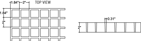
1" Thick 44% Open
| Span (inches) | CONCENTRATED LOAD in lb/ft of width | Max Load (lb/ft) | Apparent EI x 106 (lb-in2) | |||||||
|---|---|---|---|---|---|---|---|---|---|---|
| 50 | 100 | 150 | 200 | 250 | 500 | 1000 | 2000 | |||
| 12 | 0.003 | 0.006 | 0.012 | 0.031 | 0.045 | 0.059 | 0.089 | 0.120 | 1239 | 0.599 |
| 18 | 0.012 | 0.024 | 0.049 | 0.125 | 0.188 | 0.254 | 0.389 | 826 | 0.486 | |
| 24 | 0.029 | 0.057 | 0.116 | 0.295 | 0.456 | 0.580 | 620 | 0.494 | ||
| 30 | 0.059 | 0.116 | 0.233 | 0.605 | 496 | 0.478 | ||||
| 36 | 0.088 | 0.175 | 0.360 | 413 | 0.549 | |||||
| 42 | 0.171 | 0.346 | 354 | 0.448 | ||||||
| 48 | 0.262 | 0.524 | 310 | 0.439 | ||||||
| 54 | 0.345 | 0.685 | 275 | 0.447 | ||||||
| Span (inches) | UNIFORM LOAD in lb/ft of width | Max Load (lb/ft) | Apparent EI x 106 (lb-in2) | |||||||
|---|---|---|---|---|---|---|---|---|---|---|
| 50 | 100 | 150 | 200 | 250 | 500 | 1000 | 2000 | |||
| 12 | 0.002 | 0.005 | 0.007 | 0.009 | 0.011 | 0.023 | 0.046 | 0.091 | 2480 | 0.599 |
| 18 | 0.011 | 0.021 | 0.032 | 0.043 | 0.053 | 0.106 | 0.213 | 0.425 | 1425 | 0.486 |
| 24 | 0.033 | 0.066 | 0.098 | 0.131 | 0.164 | 0.328 | 825 | 0.494 | ||
| 30 | 0.077 | 0.154 | 0.230 | 0.307 | 0.384 | 536 | 0.478 | |||
| 36 | 0.168 | 0.336 | 0.504 | 310 | 0.549 | |||||
| 42 | 0.323 | 0.645 | 250 | 0.448 | ||||||
| 48 | 0.537 | 0.439 | ||||||||
| Properties Per Foot of Width | # of Bars | Load Bar Width | Bar Centers | Weight/sq ft |
|---|---|---|---|---|
| A = 2.47 in2 I = 0.16 in4 S = 0.34 in3 | 8 | 0.25" | 0.75" | 4.06 |
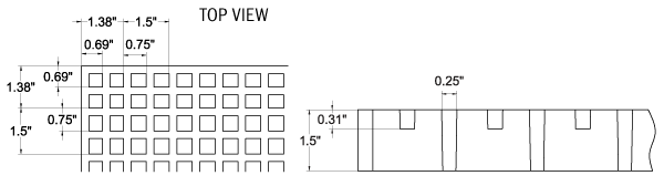
1½" Thick 44% Open
| Span (inches) | CONCENTRATED LOAD in lb/ft of width | Max Load (lb/ft) | Apparent EI x 106 (lb-in2) | |||||||
|---|---|---|---|---|---|---|---|---|---|---|
| 50 | 100 | 150 | 200 | 250 | 500 | 1000 | 2000 | |||
| 12 | 0.002 | 0.003 | 0.005 | 0.006 | 0.008 | 0.016 | 0.032 | 0.063 | 3090 | 1.14 |
| 18 | 0.004 | 0.009 | 0.013 | 0.017 | 0.021 | 0.043 | 0.085 | 0.170 | 2060 | 1.43 |
| 24 | 0.009 | 0.018 | 0.026 | 0.035 | 0.044 | 0.088 | 0.176 | 0.352 | 1545 | 1.64 |
| 30 | 0.016 | 0.032 | 0.048 | 0.064 | 0.080 | 0.160 | 0.321 | 0.642 | 1236 | 1.75 |
| 36 | 0.027 | 0.053 | 0.080 | 0.106 | 0.133 | 0.266 | 0.532 | 1030 | 1.83 | |
| 42 | 0.041 | 0.083 | 0.124 | 0.165 | 0.207 | 0.413 | 883 | 1.87 | ||
| 48 | 0.060 | 0.121 | 0.181 | 0.242 | 0.302 | 0.605 | 773 | 1.90 | ||
| 54 | 0.085 | 0.170 | 0.255 | 0.339 | 0.424 | 687 | 1.93 | |||
| 60 | 0.116 | 0.232 | 0.347 | 0.463 | 0.579 | 618 | 1.94 | |||
| Span (inches) | UNIFORM LOAD in lb/ft of width | Max Load (lb/ft) | Apparent EI x 106 (lb-in2) | |||||||
|---|---|---|---|---|---|---|---|---|---|---|
| 50 | 100 | 150 | 200 | 250 | 500 | 1000 | 2000 | |||
| 12 | <0.001 | 0.002 | 0.003 | 0.004 | 0.005 | 0.010 | 0.020 | 0.039 | 6180 | 1.14 |
| 18 | 0.004 | 0.008 | 0.012 | 0.016 | 0.020 | 0.040 | 0.080 | 0.159 | 2747 | 1.43 |
| 24 | 0.011 | 0.022 | 0.033 | 0.044 | 0.055 | 0.110 | 0.220 | 1545 | 1.64 | |
| 30 | 0.025 | 0.050 | 0.075 | 0.100 | 0.125 | 0.251 | 0.502 | 989 | 1.75 | |
| 36 | 0.050 | 0.100 | 0.149 | 0.199 | 0.249 | 0.498 | 687 | 1.83 | ||
| 42 | 0.090 | 0.181 | 0.271 | 0.362 | 0.452 | 505 | 1.87 | |||
| 48 | 0.151 | 0.302 | 0.454 | 0.605 | 386 | 1.90 | ||||
| 54 | 0.239 | 0.477 | 305 | 1.93 | ||||||
| 60 | 0.362 | 247 | 1.94 | |||||||
| Properties Per Foot of Width | # of Bars | Load Bar Width | Bar Centers | Weight/sq ft |
|---|---|---|---|---|
| A = 3.29 in2 I = 0.74 in4 S = 0.90 in3 | 8 | 0.25" | 0.75" | 4.75 |
1 1/8" Thick Covered
| Span (inches) | CONCENTRATED LOAD in lb/ft of width | Max Load (lb/ft) | Apparent EI x 106 (lb-in2) | |||||||
|---|---|---|---|---|---|---|---|---|---|---|
| 50 | 100 | 150 | 200 | 250 | 500 | 1000 | 2000 | |||
| 12 | 0.006 | 0.011 | 0.017 | 0.023 | 0.029 | 0.057 | 0.114 | 1189 | 0.31 | |
| 18 | 0.018 | 0.035 | 0.053 | 0.071 | 0.089 | 0.177 | 934 | 0.34 | ||
| 24 | 0.040 | 0.080 | 0.120 | 0.160 | 0.199 | 0.399 | 668 | 0.36 | ||
| 30 | 0.076 | 0.152 | 0.228 | 0.304 | 0.380 | 534 | 0.37 | |||
| 36 | 0.128 | 0.256 | 0.384 | 0.512 | 0.640 | 360 | 0.38 | |||
| Span (inches) | UNIFORM LOAD in lb/ft of width | Max Load (lb/ft) | Apparent EI x 106 (lb-in2) | |||||||
|---|---|---|---|---|---|---|---|---|---|---|
| 50 | 100 | 150 | 200 | 250 | 500 | 1000 | 2000 | |||
| 12 | 0.004 | 0.007 | 0.011 | 0.014 | 0.018 | 0.036 | 0.071 | 0.143 | 2378 | 0.31 |
| 18 | 0.017 | 0.033 | 0.050 | 0.066 | 0.083 | 0.166 | 0.332 | 1245 | 0.34 | |
| 24 | 0.050 | 0.100 | 0.150 | 0.199 | 0.249 | 0.498 | 668 | 0.36 | ||
| 30 | 0.119 | 0.237 | 0.356 | 0.475 | 0.593 | 427 | 0.37 | |||
| 36 | 0.240 | 0.480 | 240 | 0.38 | ||||||
| 42 | 0.431 | 205 | 0.39 | |||||||
| Properties Per Foot of Width | # of Bars | Load Bar Width | Bar Centers | Weight/sq ft |
|---|---|---|---|---|
| A = 1.79 in2 I = 0.15 in4 S = 0.30 in3 | 8 | 0.25" | 1.5" | 2.73 |
- The above tables were developed in accordance with the test method developed by the Fiberglass Grating Manufacturers Council (FGMC) of the American Composites Manufacturers Association (ACMA) for the Fiberglass Grating Standard.
- The designer should not exceed MAXIMUM RECOMMENDED load at any time. MAXIMUM LOAD represents a 4:1 factor of safety on ULTIMATE CAPACITY. ULTIMATE CAPACITY represents MAX LOAD observed at initial fracture.
- Walking loads for maintenance traffic are typically a live load of 50 PSF. Deflections for worker comfort are typically limited to 0.375" or SPAN divided by 120 under full live load. For a firmer feel under full live load or a line load 250 lb/ft of width, limit deflections to 0.25" or SPAN divided by 200.
- The loads represented are for STATIC LOAD CONDITIONS at ambient temperature. Deflections for impact loads or dynamic loads will MULTIPLY the deflections shown by 2. Long term loads will result in added deflection due to creep in the material and will require higher factors of safety to ensure acceptable performance.
- Deflections are limited to 0.5" as recommended by the Fiberglass Grating Manufacturers Council of the American Composites Manufacturers Association.
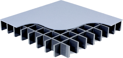
High Load Capacity Molded Grating
High Load Capacity (HLC) molded grating is high-strength, corrosion-resistance and low-maintenance, like our traditional molded grating, with the added bonus of being engineered to carry higher loads than traditional grating. Our molded HLC grating is available in 4' x 6' panels with 1½" and 2" thickness and comes in GPFR, IFR and VFR resin systems in standard gray color.
Features
- High strength
- Corrosion resistant
- Low conductivity
- Fire retardant
- Low maintenance
Applications
- Flooring, platforms and ramps
- Storage areas
- Assembly lines
- Long-span walkways
- Trench covers with vehicular traffic
Available Resin Systems
HLC molded grating is available in three resin systems, each providing different levels of corrosion protection. All three resin systems meet Class 1 Flame Spread Rating per ASTM E-84 test standards.
GPFR: A general-purpose orthophthalic polyester resin system that offers good corrosion resistance at an economical price.
IFR: A premium-grade isophthalic polyester resin system that provides excellent corrosion protection.
VFR: A vinylester resin system that provides the highest level of corrosion protection.
To view load data for our molded grating, click on a size below.
1½" Thick 48% Open
| Span (inches) | CONCENTRATED LOAD in lb/ft of width | Max Load (lb/ft) | ||||||
|---|---|---|---|---|---|---|---|---|
| 200 | 500 | 1000 | 2000 | 3000 | 4000 | 5000 | ||
| 18 | <0.01 | 0.02 | 0.04 | 0.07 | 0.11 | 0.15 | 0.19 | 28,047 |
| 24 | 0.02 | 0.04 | 0.09 | 0.17 | 0.26 | 0.34 | 0.44 | 20,430 |
| 36 | 0.06 | 0.14 | 0.28 | 13,620 | ||||
| 42 | 0.09 | 0.22 | 0.44 | 11,619 | ||||
| Span (inches) | UNIFORM LOAD in lb/ft of width | Max Load (lb/ft) | |||||
|---|---|---|---|---|---|---|---|
| 200 | 400 | 500 | 600 | 700 | 800 | ||
| 18 | <0.01 | 0.01 | 0.02 | 0.02 | 0.02 | 0.03 | 36,000 |
| 24 | 0.02 | 0.04 | 0.05 | 0.06 | 0.08 | 0.09 | 20,390 |
| 36 | 0.10 | 0.21 | 0.26 | 0.31 | 0.37 | 0.42 | 8,814 |
| 42 | 0.19 | 0.39 | 0.48 | 6,550 | |||
| Properties Per Foot of Width | # of Bars | Load Bar Width | Bar Centers | Weight/sq ft |
|---|---|---|---|---|
| A = 7.2 in2 I = 1.35 in4 S = 1.75 | 12 | T-.43 / B-.35 | 1" | 6.21 |
2" Thick 48% Open
| Span (inches) | CONCENTRATED LOAD in lb/ft of width | Max Load (lb/ft) | ||||||
|---|---|---|---|---|---|---|---|---|
| 200 | 500 | 1000 | 2000 | 3000 | 4000 | 5000 | ||
| 18 | <0.01 | 0.01 | 0.03 | 0.05 | 0.07 | 0.10 | 0.13 | 32,651 |
| 24 | 0.02 | 0.03 | 0.06 | 0.11 | 0.17 | 0.22 | 0.27 | 27,245 |
| 36 | 0.04 | 0.09 | 0.17 | 0.34 | 0.51 | 18,130 | ||
| 42 | 0.05 | 0.13 | 0.26 | 15,525 | ||||
| Span (inches) | UNIFORM LOAD in lb/ft of width | Max Load (lb/ft) | |||||
|---|---|---|---|---|---|---|---|
| 200 | 400 | 500 | 600 | 700 | 800 | ||
| 18 | <0.01 | 0.01 | 0.01 | 0.01 | 0.01 | 0.01 | 43,494 |
| 24 | 0.01 | 0.02 | 0.03 | 0.04 | 0.04 | 0.05 | 27,195 |
| 36 | 0.06 | 0.12 | 0.15 | 0.18 | 0.21 | 0.24 | 8,795 |
| 42 | 0.11 | 0.22 | 0.28 | 0.33 | 0.39 | 0.44 | 8,795 |
| Properties Per Foot of Width | # of Bars | Load Bar Width | Bar Centers | Weight/sq ft |
|---|---|---|---|---|
| A = 7.2 in2 I = 1.35 in4 S = 1.75 | 12 | T-.47 / B-.35 | 1" | 8.4 |
- The above tables were developed in accordance with the test method developed by the Fiberglass Grating Manufacturers Council (FGMC) of the American Composites Manufacturers Association (ACMA) for the Fiberglass Grating Standard.
- The designer should not exceed MAXIMUM RECOMMENDED load at any time. MAXIMUM LOAD represents a 4:1 factor of safety on ULTIMATE CAPACITY. ULTIMATE CAPACITY represents MAX LOAD observed at initial fracture.
- Walking loads for maintenance traffic are typically a live load of 50 PSF. Deflections for worker comfort are typically limited to 0.375" or SPAN divided by 120 under full live load. For a firmer feel under full live load or a line load 250 lb/ft of width, limit deflections to 0.25" or SPAN divided by 200.
- The loads represented are for STATIC LOAD CONDITIONS at ambient temperature. Deflections for impact loads or dynamic loads will MULTIPLY the deflections shown by 2. Long term loads will result in added deflection due to creep in the material and will require higher factors of safety to ensure acceptable performance.
- Deflections are limited to 0.5" as recommended by the Fiberglass Grating Manufacturers Council of the American Composites Manufacturers Association.